Vibration analysis on a conveyor drive unit
The inscription on the James Farley Post Office in New York City reads:
“Neither snow nor rain nor heat nor gloom of night stays these couriers from the swift completion of their appointed rounds.”
Though climate is something beyond control, maintaining machine health in postal facilities and keeping the mail moving is something that can be achieved. The United States Postal Service processes large bundles, packages, and catalogues through 21 Bulk Mail Centers (BMC) around the nation. These centers are filled with motors, conveyors, speed reducing gearboxes, and various other material handling equipment that operates 24 hours a day during peak demand periods. Keeping those machines operational is a daunting task.
In an ongoing effort to increase machine reliability and reduce overall costs, the USPS Maintenance Technical Support Center in Norman, Oklahoma initiated a project to provide the BMC maintenance offices with vibration analysis equipment and training to help support the maintenance process.
This case history helps illustrate some of the benefits gained through the use of this technology.
The B-14 conveyor drive was classified as a critical drive for the movement of mail through the Cincinnati BMC. Early in the program, vibration testing identified serious intermediate shaft looseness or impacting problem with the drive unit on B-14. The intermediate shaft vibration levels were monitored closely and trended for increased vibration. Through the Christmas season, the unit showed increased vibration levels indicating that the problem was getting worse. But by trending the results, the maintenance staff could make an educated decision to wait to replace parts. A replacement to the gearbox was made during a scheduled maintenance period before catastrophic failure mitigating production loss and downtime.
When the unit was replaced, the maintenance technicians disassembled the defective gearbox and found a broken tooth on the low speed pinion. The broken tooth was causing an impact each time it meshed with the gear on the output shaft. The tooth next to the broken tooth also had a severe crack and came off when handled by the analyst. The photographs below show the intermediate shaft on the left and the broken teeth on the right.

Benefits
Represented in this case history are two obvious benefits to any organization with critical machinery where down time creates a hardship.
First, the vibration technicians were able to identify a significant problem on a critical unit and continue to evaluate the risk of continued operation over the five months they needed to run it. Second, they were able to anticipate the parts required for repair, order them, and schedule the repair before failure occurred.
Catastrophic failure usually causes collateral damage (which results in significantly more down time and repair costs) and typically happens at the worst possible time. By implementing a predictive maintenance program, an organization can increase uptime and avoid production loss.
The details
This case history displays some of the vibration data used in the diagnosis of the problem. A basic explanation of the internal configuration of the gearbox is included to help you understand the machine. The driver is a 4 pole AC induction motor operating at a speed of about 1785 cpm. The motor / gearbox is close coupled and the double reduction gearbox has two gear meshes that are identified as high speed gear mesh (HG) and low speed gear mesh (LG). The shaft rate frequencies and gear mesh frequencies were calculated using the gear teeth ratios. See Figure 1 below.

Vibration setup
The maintenance staff used a triaxial accelerometer sensor to collect vibration data in three axes (axial, radial, and tangential). The DC-7B digital data collector was configured for 800 line vibration data using both the Fast Fourier Transform (FFT) and amplitude demodulation (DEMOD) signal processing techniques. The FFT spectra were collected using two frequency ranges. The low range data covers a range from 0 to 150 Hz, and the high range data is from 0 to 1500 Hz. The DEMOD spectra were collected using a frequency range from 0 to 300 Hz.
Vibration spectral data
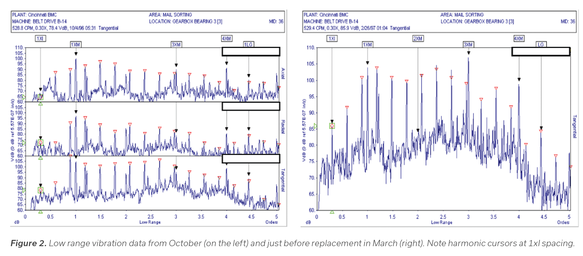
The first vibration test was conducted in early October. The prime mover was replaced in early March of the following year. Figure 2 shows the first and last set of data taken on the faulty machine. The tangential spectrum shows a strong 1xI harmonic series.
Note that all prominent peaks in the spectra are harmonics of either 1xM or 1xI.


Vibration demod data
The DEMOD spectra are shown in triaxial format in Figure 4a for the October data set. The February data is shown in Figure 4b. The harmonic spacing is clearly at a frequency that corresponds to 1xI. Note that the noise floor is higher for the February data while the amplitudes in the harmonic series are slightly lower.


Vibration analysis
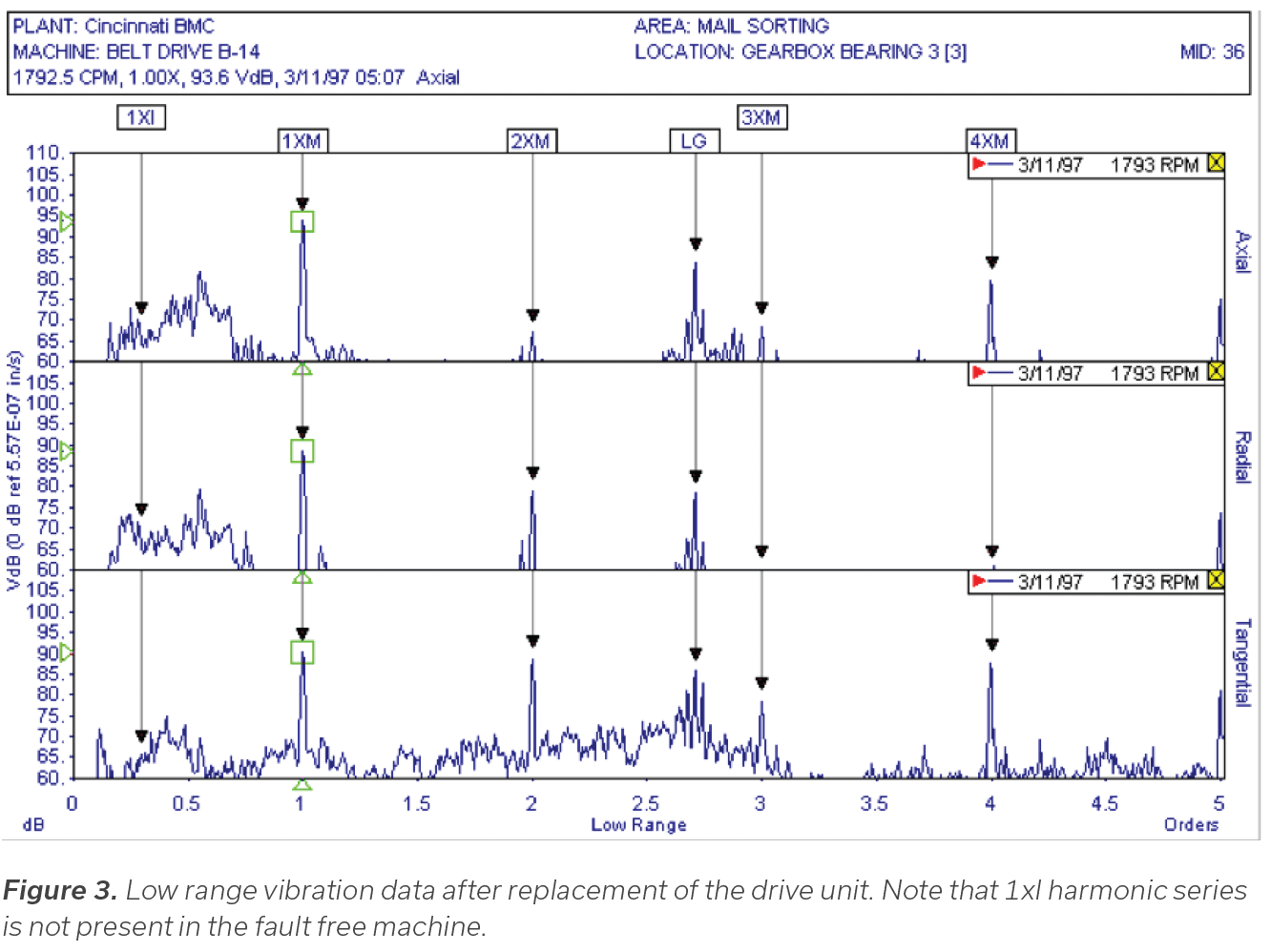
The first vibration test showed a significant intermediate shaft rate (1xI) harmonic series in the FFT spectra (figure 2). The strong 1xI harmonic series in the DEMOD spectra (figure 4) confirms the intermediate shaft problem and actually shows the fault much more clearly. The shaft rate harmonic series with high amplitudes indicates looseness or impacting problem with the intermediate shaft or one of the components on the shaft. The maintenance technicians continued to monitor the machine on a monthly basis until a replacement was available and the conveyor could be taken out of service. Each monthly survey showed the strong 1xI harmonic series up to the point of replacement.
Based on the findings of the disassembled gearbox, if left to run until complete failure, the low speed pinion would have continued its self-destruction and catastrophic failure would have probably been the result.
Conveyors and similar equipment can be found across multiple industries. Predictive condition-based monitoring of those assets can help anticipate repairs and assist in vital production maintenance decisions.


